 |
| October 06, 2015 | Volume 11 Issue 37 |
Designfax weekly eMagazine

Archives
Partners
Manufacturing Center
Product Spotlight
Modern Applications News
Metalworking Ideas For
Today's Job Shops
Tooling and Production
Strategies for large
metalworking plants
Design Tip:
The ins and outs of proper threading
By Gus Breiland, Customer Service Engineering Manager, Proto Labs
You can easily add threaded holes to your machined parts at Proto Labs, and the addition of turning capability has created even more threading options. There are two basic types of machined threads: internal threads and external threads.
Internal threads
Internal threads are machined using a single-lip threading tool -- not a traditional threading tap. On parts with internal hole features in need of threading, the actual threads need to be removed from your CAD model, leaving only the pilot diameter. Our software recognizes a hole for threading if:
- It falls within the diameter range for the desired thread, and
- It is in one of the three cardinal axes for milling, or
- It is perpendicular to the axis of revolution for turning.
Proto Labs supports right-hand threaded holes on machined parts for UNC and UNF threads ranging from a #2 and up to a 1/2 in.; metric threads are also available ranging from M2 to M12. Location and method of manufacturing may limit some threads from becoming eligible.
Another key factor to keep in mind is our maximum depths for threads based on our threading tools. Our #2 threads have a maximum thread depth from the top of surrounding features of 0.200 in. and our 1/2-in. threads can go much deeper -- up to 1 in. of threading depth is available. For metric threads, capabilities range from 5.08 mm and 25.4 mm in depth. Thread depths will gradually increase as the diameter of the threads increases. More on that later in the design tip.
Internal threads are also available on turned parts. Many of the same rules apply for machining threads using live tooling on a lathe, but the available threads are more limited than milling. UNC and UNF threads range from #4-40 to 1/2-20 and metric threads from M3 to M10. With the addition of live tooling, we are able to produce threaded features radially, axially, and on-axis. This impacts the threading, as some threads are available on-axis only. Please pay close attention to your quote or contact a customer service engineer for further clarification. A complete chart of turned threaded holes is available at protolabs.com, and be sure to select turned parts under standard holes to view the availability of these options.
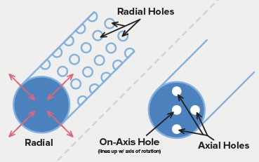
Figure 1: This illustration shows the three different types of holes that are possible on turned parts.
In machining internal threaded holes, a hole may oftentimes be longer than what our threading tools are able to reach. In this case, you have a few options depending on your needs:
- With a long through hole that exceeds the maximum reach, select the hole from the side that you anticipate the screw to be started from as shown in image 1. If your screw is required to pass the entire way through the part, you would also have to pass a tap through the hole (in a secondary process) to complete it.
- You can also select both sides of the feature to be threaded as shown in Figure 2, but notice the maximum thread depths as they overlap with each other in the hole. This raises concern with threading the features from both sides; you risk the threat of being cross-threaded, and a screw may not pass all the way through the part cleanly. But as long as the threads don't intersect as seen in the last image in Figure 3, selecting threads from both sides is typically fine.
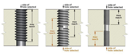
Figure 2: Three methods of approaching maximum thread depths.
External threads
The introduction of lathe has improved our external threading capabilities, and you can now get external threads for select sizes as long as your part qualifies for turning. We still use a custom threading tool with a selected number of thread sizes, depths, and placements within the part geometry. However, Proto Labs' advanced turning process offers external threads on the centerline of the part as well as live tooling that allows for internal holes to be threaded as long as they follow similar guidelines as milling. And it's not limited to on-axis holes -- axial and radial holes are also available.
Just like internal threads, external thread design for turned parts needs to have the thread removed from the CAD model in order for our software to recognize it. Additionally, please model your external threads for milling; don't model them for turning. After you receive your quote for turning, you will then have the ability to select the appropriate thread size.
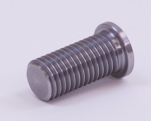
Figure 3: A finished piece with external threads that has been turned on a lathe.
External milled threads are designed into parts much less frequently than internal threads, but nonetheless, they can still be machined effectively. External milled threads are produced on the half diameter, and then the part is rotated 180 degrees where the opposing threads are machined in the same way. If you have larger, coarse external threads, this does work well -- we're able to produce quality 1/2-in. threads, but you may still want to chase the threads to remove any remaining material or mismatch as the threads are produced in two different machining setups.
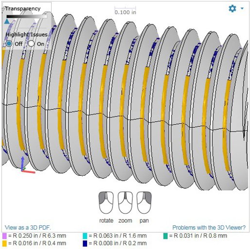
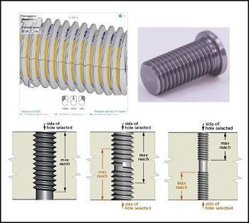
Figure 4: This CAD model illustrates an as-milled view of an external thread with resulting radii highlighted in yellow. This would be for milled parts only.
Smaller external threads such as a #6-32 are much more difficult to produce with a ball or flat endmill, as a larger radii would be left in the root of the thread since the pitch is too tight. You would be required to chase the threads with a thread-cutting die in order to remove the remaining material. On many parts, a 0.008-in. to 0.016-in. radius would be left.
Coil inserts
Coil inserts are also available if you require stronger threads. Coil insert threads are applied to the holes, but the coil inserts are not installed during manufacturing. The inserts would need to be installed by the user after the part is manufactured, but before the part can be assembled. Coil Inserts are available in UNC and UNF threads ranging from a #2 to 1/2 in., and metric from M2 to M12 with the same depths as standard threaded holes. Proto Labs is optimized for HeliCoil brand inserts, and we recognize standard sizes and lengths.
Threading in CAD programs
Many CAD packages allow you to display threaded features in a couple different ways, including tap drill, cosmetic thread, or by the major diameter of the thread. We suggest selecting the pilot diameter as long as it is designed at approximately 75% of the thread diameter.
The CAD file should then be submitted in a file format other than STL; we discourage uploading STL file formats for machined parts, as our software is unable to recognize features like pilot holes in that format. A neutral file format such as IGES or STEP should be used if possible.
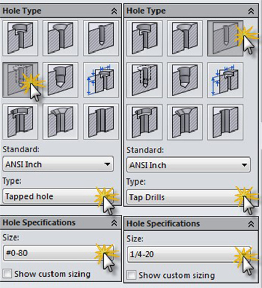
Figure 5: A pilot hole is designed -- before threading -- into a CAD model in Solidworks.
On milled parts that require external threads, you must design the threads on your part, as this would then be in our standard milling procedure that uses ball and flat end mills. As stated earlier, this would not be the preferred method for producing threads, as you may be required to perform a secondary process of chasing a cutting die over the threads to ensure the parts can be assembled correctly.
On turned parts, external threading improves greatly because the part is spinning on center and a sharp, single-lip threading tool can produce a quality thread. The design of an external turned thread is similar to that of the internal hole. You must remove the threads so software can digital view the outside diameter to determine the type of thread needed.
Threading in quotes
Within your Proto Labs quote, you have the ability to select both internal and external threads on part features. On the Thread Assignment tab of your quote, you will notice a fully interactive model that allows you to select the threaded features that are available. Each eligible feature will be highlighted, and you can manually select threads. Threads can also be mass-assigned in UNC, UNF, and metric, which can be faster than assigning threads to individual holes, but be aware that you might inadvertently thread holes you weren't intending to.
If a thread you want isn't available, you may need to double check the diameter of your features to make sure they are within the guidelines for threading. Note that while reviewing our threading charts, you can toggle between our milled and turned options within each tab to review the availability of threads for each method of manufacturing. All threads need to be selected and saved before proceeding with an order. If you change your manufacturing process or material at any point, please check the Thread Assignment tab again as selections may change.
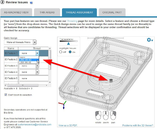
Within Proto Labs' interactive quotes, you can assign threaded features on your CAD model.
Proto Labs offers threaded features for milled parts in plastic and metal, and threaded features on turned parts are only available in metal materials at this time. We can accommodate UNC, UNF, and metric threads along with coil inserts (but do not supply or install the coil inserts). For a complete list of milled and turned threading guidelines, click here. If you have any remaining questions on threading, feel free to contact a customer service engineer at customerservice@protolabs.com or 877.479.3680.
Published October 2015
Rate this article
View our terms of use and privacy policy